close
Choose Your Site
Global
Social Media
Views: 0 Author: Site Editor Publish Time: 2026-10-30 Origin: Site


Battery safety devices present a frustrating operational paradox on the plant floor. The exact component engineered to prevent catastrophic explosions often becomes the primary cause of failure when neglected. Industrial and standby power systems rely heavily on flame arrestors to safely vent volatile hydrogen and oxygen gases while simultaneously blocking external ignition sources. However, battery flame arrestor clogging fundamentally restricts this necessary off-gassing. This restriction traps gases, leading to dangerous internal pressurization. It compromises battery case integrity and introduces severe facility and personnel safety risks.
Mitigating these hazards requires moving far beyond basic visual checks. Facility managers must implement rigorous, evidence-based inspection protocols. You need maintenance frameworks that align directly with strict industrial safety standards. Relying on superficial observations leaves critical infrastructure vulnerable to sudden, violent structural failures.
Clogging Mechanisms: Flame arrestors primarily fail due to the crystallization of electrolyte mist, environmental dust ingress, and material degradation over time.
Pressurization Risks: A blocked vent fundamentally alters the internal pressure dynamics of the cell, risking case rupture, acid leakage, and explosive hydrogen accumulation.
Diagnostic Necessity: Effective sintered battery vent inspection requires measuring flow resistance and pressure drops, not just relying on superficial visual assessments.
Maintenance Economics: Proactive battery flame arrestor maintenance prevents premature battery replacement and mitigates the severe liability of workplace safety incidents and flame propagation.
Industrial battery environments operate as specialized volatile liquid enclosures. Continuous and unobstructed off-gassing keeps the system stable and prevents internal pressure from exceeding the mechanical limits of the plastic casing. Physical and chemical processes constantly threaten this venting pathway. Understanding these mechanisms helps operators prevent failures before they initiate on the racks.
The normal off-gassing process carries microscopic droplets of electrolyte. In lead-acid systems, this means highly corrosive sulfuric acid travels upward into the venting structure during every charge cycle. These droplets enter the complex, porous matrix of the arrestor material. Once inside, the liquid component evaporates into the surrounding air, driven by the ambient heat of the battery room and the internal heat generated by the charging process.
This evaporation leaves behind solid sulfate crystals. Over successive charge and discharge cycles, especially during high-voltage equalization charges, these crystals accumulate heavily. They form dense flame arrestor electrolyte deposits deep within the material. This crystallization process steadily chokes the available escape routes for internal gases. The buildup remains completely invisible from the outside. It occurs deep within the microscopic pores of the sintered disc, slowly reducing the functional open area of the vent until gas can no longer pass through at the required rate.
Internal chemistry represents only half the problem. Ambient facility conditions heavily influence vent longevity and performance. Manufacturing environments often contain high levels of airborne particulates. Dust, dirt, and industrial debris constantly circulate in the air. High ambient humidity exacerbates this issue significantly by introducing moisture that helps bind these particles together.
The sticky electrolyte residue inside the vent acts like a magnet. It catches and holds airborne contaminants that settle on the battery cover. This creates a highly destructive interaction. The combination of solid sulfate crystals and external dirt forms a thick, impermeable paste. This paste hardens over time, accelerating pore blockage. Arrestors in harsh, unfiltered environments fail much faster than those in clean, climate-controlled rooms.
Contaminant Source | Mechanism of Accumulation | Impact on Vent Porosity |
|---|---|---|
Sulfuric Acid Mist | Evaporates inside the vent pores during normal off-gassing. | Forms hard sulfate crystals that permanently reduce pore diameter. |
Airborne Facility Dust | Settles on the vent exterior and gets pulled into surface pores. | Mixes with acid residue to create a thick, cement-like paste. |
High Ambient Humidity | Introduces excess moisture into the vent matrix. | Accelerates the agglomeration of dust and sulfate particles. |
Manufacturing Debris | Metal shavings or chemical dust from nearby processes. | Causes rapid surface blinding of the sintered disc. |
Pressure drop represents the difference in pressure between the inside of the battery and the outside atmosphere as gas flows through the vent. A healthy vent maintains a very low pressure drop, allowing gas to escape freely without building up behind the disc. As pore volume decreases due to clogging, flow resistance increases exponentially. This causes the internal cell pressure to spike rapidly, forcing the battery casing to absorb the stress.
You must monitor the battery vent pressure drop to understand the actual health of the system. Exceeding the maximum flow rate capacity of a partially clogged arrestor creates a dangerous situation. During high-charge states, the battery generates gas rapidly. If the vent cannot release this gas fast enough, the system overloads. The internal pressure quickly surpasses safe operating limits, setting the stage for mechanical failure and potential acid spills.
A clogged arrestor progresses predictably from a minor maintenance issue to a critical safety failure. Evaluating these outcomes helps prioritize intervention and justifies the resources spent on preventative maintenance across large-scale power systems.
When gas cannot escape, the battery casing absorbs the mechanical stress. You will notice physical signs when a lead acid battery flame arrestor blocked by debris reaches a critical state. The most obvious sign is case bulging. The plastic walls of the jar bow outward under the sustained internal load. You may also observe cover-to-jar seal separation, where the adhesive or weld holding the top cover begins to fail under the constant upward pressure.
Every battery casing has strict mechanical limits designed by the manufacturer. Once internal pressure exceeds this threshold, structural failure becomes imminent. The plastic can crack, or the entire top can blow off violently. This ruins the battery, spills acid across the racks, and creates an immediate hazard for any technicians working in the aisle.
Initial Pore Restriction: Gas flow slows down, causing a slight, often unnoticeable increase in internal pressure during equalization charges.
Seal Stress: The cover-to-jar weld begins to experience sustained outward force, weakening the adhesive bond over several weeks.
Visible Deformation: The sides of the battery jar begin to bulge outward. This is a clear visual indicator of severe internal pressurization.
Micro-Cracking: Hairline fractures develop around the terminal posts and the vent well, allowing trace amounts of acid gas to escape.
Catastrophic Rupture: The casing exceeds its tensile strength, resulting in a violent structural failure and massive acid spill.
Lead-acid batteries generate hydrogen and oxygen continuously during charging. Trapped hydrogen creates severe stoichiometric risks within the cell headspace. A concentration of just 4% hydrogen in air becomes explosive. A clogged arrestor traps these gases, building a highly volatile mixture directly above the internal plates where electrical connections reside.
This blockage also negates the flame-quenching design of the vent itself. The arrestor cools and extinguishes any external flame before it enters the cell. If the vent is blocked and internal pressure causes a structural rupture, the gas escapes unpredictably. An internal spark from a broken weld or a short circuit can ignite this trapped gas. This turns a simple blockage into a catastrophic rupture. The resulting explosion risks flame propagation to adjacent battery cells, endangering critical infrastructure and personnel safety.
Pressure-induced seal failures rarely happen cleanly. They often lead to undetected, slow electrolyte loss. As the cover seal separates, acid leaks out down the sides of the jar and pools on the battery racks. This lowers the electrolyte level inside the cell, exposing the active plate material to air and permanently damaging the battery capacity.
Electrolyte dry-out directly increases internal electrical resistance. Higher resistance generates localized heating during charge and discharge cycles. This heat accelerates the chemical reactions, generating even more gas and heat. This dangerous feedback loop initiates thermal runaway. The battery effectively cooks itself from the inside out, melting the casing and potentially catching fire. A simple blocked vent initiates this entire destructive sequence.
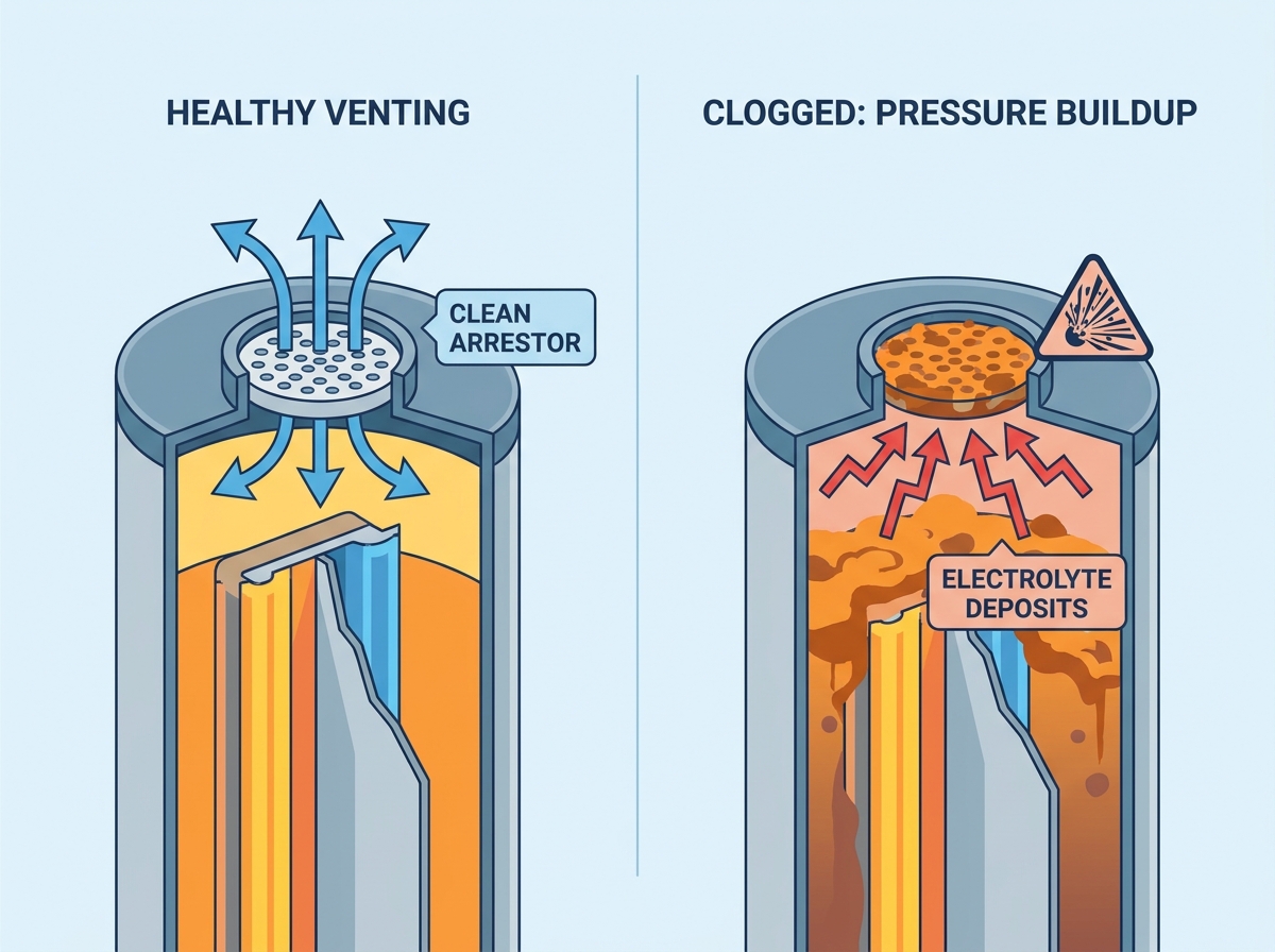
Identifying blockages before they cause structural damage requires specific technical methodologies. You cannot rely on guesswork or simple visual scans to determine the health of micro-porous materials. You need hard data to make informed maintenance decisions.
Naked-eye inspections have severe limitations. Sintered materials are micro-porous, meaning the gas pathways remain microscopic. You cannot see deep inside the structure to identify internal scaling. A vent might look perfectly clean on the surface but be completely blocked internally by crystallized acid. Relying solely on visual checks provides a false sense of security.
Instrumental approaches are mandatory for accurate sintered battery vent inspection. Back-pressure testing forces a measured amount of inert gas through the vent to read resistance using a digital manometer. Ultrasonic cleaning assessments measure the weight and permeability of the vent before and after sonic agitation. These tools provide objective, quantifiable data about the internal condition of the arrestor, removing human error from the diagnostic process.
Inspection Method | What It Detects | Limitations |
|---|---|---|
Visual Surface Scan | Heavy external dust buildup, obvious physical damage, or missing O-rings. | Cannot detect internal sulfate crystallization or deep pore blockages. |
Back-Pressure Testing | Exact flow resistance and internal pore restriction levels. | Requires specialized, intrinsically safe testing equipment and inert gas. |
Weight Comparison | Accumulation of solid mass (sulfates/dirt) inside the vent structure. | Requires an accurate baseline weight of the vent when brand new. |
Ultrasonic Assessment | Permeability changes before and after deep sonic cleaning. | Time-consuming and requires removing the vent from active service. |
Catching a battery vent blockage early saves equipment and prevents accidents. Look for localized condensation around the vent cap, which suggests gas struggles to escape and is cooling rapidly at the restriction point. Listen for unusual hissing sounds during charge cycles. This indicates gas forcing its way through restricted paths or compromised seals. Inspect the plastic for micro-cracks near the vent well.
You must also check for concurrent corrosion around the vent well. Acid mist escaping from a poor seal corrodes nearby terminals rapidly, turning them green or white. Inspect the gasket and O-ring for wear. A degraded O-ring compromises the seal and masks internal pressure issues by allowing gas to bypass the arrestor entirely. Establish a strict timeline for routine diagnostic checks. Base this schedule on your specific battery duty cycles and the harshness of the environmental conditions.
Every flame arrestor has specific performance metrics engineered by the manufacturer. You need a framework for reviewing manufacturer data sheets. Look specifically for the maximum acceptable pressure drops and maximum flow rates. These numbers dictate the safe operating window for the vent under load. Operating outside these parameters guarantees eventual failure.
When testing flow rates, safety remains paramount. Never introduce ignition risks during the diagnostic process. Use intrinsically safe equipment. Perform back-pressure tests using nitrogen or another inert gas. Compare your measured resistance against the baseline data sheet specifications. Any significant deviation indicates restricted flow and requires immediate intervention.
Maintaining vent integrity without compromising flame-quenching properties requires actionable frameworks. Mishandling these components introduces new risks and destroys the safety mechanisms you want to preserve. Technicians must follow strict procedures to ensure the vents function correctly after servicing.
Washing and neutralizing flame arrestors happens frequently in many facilities. Technicians often use distilled water or specific neutralizing baths. This removes surface acid and loose dirt effectively. However, you must evaluate the efficacy of this approach carefully. Incomplete cleaning poses a major risk, as it leaves the core of the vent restricted.
If sulfate crystals remain deep in the pores, the vent remains compromised. You must establish hard criteria for when battery flame arrestor maintenance falls short. If a vent fails a back-pressure test after cleaning, complete replacement becomes mandatory. Do not attempt to drill, poke, or mechanically clear the pores with wire. This destroys the precise flame-quenching geometry and renders the device useless against an explosion.
Remove the vent carefully using the correct socket size to avoid stripping the plastic threads.
Submerge the arrestor in a dedicated neutralizing solution, typically a mild bicarbonate mix, to neutralize active sulfuric acid.
Rinse thoroughly with distilled water. Never use tap water, as mineral deposits will create new blockages inside the pores.
Allow the vent to air dry completely in a clean, dust-free environment before attempting any flow resistance testing.
Discard any vent that shows physical discoloration, brittleness, or fails to meet baseline flow metrics after a full cleaning cycle.
Removing and cleaning vents requires care. You risk damaging the fragile sintered material during handling. Dropping a ceramic or sintered plastic vent causes micro-fractures. These fractures allow flames to pass straight through the material without being quenched, completely defeating the purpose of the device.
O-rings prove equally critical to the system's integrity. Removing a vent often stretches or tears the rubber O-ring. Provide your technicians with strict torque and seating guidelines. The vent must remain gas-tight around the threads. Gas must only permeate through the arrestor disc itself. Emphasize the mandatory replacement of worn gaskets during every maintenance cycle. A perfectly clean vent paired with a bad gasket provides zero protection.
Maintenance protocols must map directly to established safety standards. Follow IEEE 450 guidelines for vented lead-acid batteries. This standard dictates specific inspection intervals, testing procedures, and documentation requirements. Adhering to these guidelines ensures your maintenance program meets industry expectations and keeps your facility compliant.
You must also comply with OSHA regulations regarding explosive gas management. Personnel protection in battery rooms remains non-negotiable. Ensure adequate ventilation and proper personal protective equipment during all maintenance tasks. Document every inspection, cleaning, and replacement meticulously. This documentation proves compliance and protects the facility from liability in the event of an incident.
Selecting replacement vents for large-scale battery plants requires careful decision-making. You must balance several overall value influencing factors to ensure long-term safety and operational efficiency. Choosing the wrong vent material or porosity can lead to rapid re-clogging or compromised safety.
The material of the arrestor dictates its performance and lifespan. Sintered plastics, like porous PTFE or polyethylene, offer excellent chemical resistance. They repel sulfuric acid effectively and resist degradation over years of service. Ceramics provide superior mechanical durability and extreme heat resistance, making them ideal for high-temperature environments where plastics might warp.
Compare the porosity consistency of both options. Consistent pore size ensures uniform gas flow across the entire disc. Discuss how material choice impacts the frequency of future clogging. Plastics resist sulfate bonding better, while ceramics withstand harsher cleaning regimens without degrading. Choose the material that best resists your specific corrosive environment and maintenance capabilities.
Arrestor Material | Chemical Resistance | Mechanical Durability | Best Application Environment |
|---|---|---|---|
Sintered Polyethylene (PE) | Excellent resistance to sulfuric acid and electrolyte mist. | Moderate. Can deform if over-torqued during installation. | Standard indoor battery rooms with controlled temperatures. |
Sintered PTFE (Teflon) | Superior chemical inertness. Resists almost all industrial chemicals. | Good. Highly flexible but requires careful handling to avoid tearing. | Highly corrosive environments or facilities with mixed chemical exposure. |
Porous Ceramics | Good acid resistance, but susceptible to strong alkaline degradation. | Very High. Withstands extreme heat and physical impacts well. | High-temperature industrial plants or heavy manufacturing zones. |
Engineers face a strict trade-off when designing these vents. Larger pores reduce clogging risks and lower pressure drops, allowing gas to escape easily. However, larger pores fail to quench a high-velocity flame front. The material must absorb enough heat to extinguish the flame before it passes through the disc and enters the volatile headspace of the battery.
You must verify that any replacement vent meets specific safety criteria. Check the Maximum Experimental Safe Gap (MESG) requirements for hydrogen. The vent's pore size must remain smaller than the MESG to prevent flame propagation. Never prioritize flow rate over flame-quenching capability. A vent that flows freely but fails to stop a fire creates a severe liability for the entire facility.
Battery flame arrestor clogging represents an inevitable chemical and environmental reality on the plant floor. You must manage it through rigorous, scheduled diagnostics rather than reactive troubleshooting. Waiting for a battery case to bulge before taking action invites catastrophic failure.
Audit your current battery maintenance logs immediately to identify any missed vent inspections or overdue replacements.
Integrate objective pressure-drop testing and mandatory gasket wear checks into your next quarterly inspection cycle.
Prioritize replacement arrestors that offer verified flow-resistance data and utilize materials highly resistant to sulfate crystallization.
Replace any vents showing signs of irreversible electrolyte scaling or physical micro-fractures without hesitation.
A: Blockages primarily result from the evaporation of electrolyte mist, which leaves behind solid sulfate crystals deep within the porous material. This internal scaling is often compounded by environmental dust, manufacturing particulates, and material corrosion, creating a dense, impermeable paste that chokes gas flow.
A: Visual indicators include physical case bulging, cover seal separation, and localized condensation. Auditory signs include a lack of normal off-gassing sounds during equalization or unusual hissing. Instrumentally, you will see measurable increases in internal pressure and flow resistance during back-pressure testing.
A: While surface neutralizing with distilled water or specific baths is possible, deep pore blockages in sintered materials are rarely cleared entirely. If a vent fails a flow test after cleaning, complete replacement is required to guarantee safety and prevent flame propagation.
A: Acceptable pressure drop varies significantly by manufacturer, vent material, and cell size. You must consult the specific data sheet for your component. Any deviation from the baseline specifications indicates restricted flow and a high risk of overloading the venting system.
A: Industry best practices recommend conducting visual checks monthly to spot early signs of bulging or leaks. Detailed instrumental inspections, including flow testing and gasket checks, should occur quarterly or semi-annually, depending heavily on the operating environment and IEEE 450 guidelines.
A: It causes it indirectly. Blockages cause internal pressure spikes, leading to seal failures and subsequent electrolyte leaks. This resulting dry-out increases internal electrical resistance, which generates excessive localized heat during charging, eventually triggering the thermal runaway cycle.