close
Choose Your Site
Global
Social Media
Views: 0 Author: Site Editor Publish Time: 2026-10-18 Origin: Site


Water filtration systems require a strict balance between chemical adsorption and hydraulic efficiency. You have to maximize adsorption kinetics while keeping hydraulic resistance low. Improper sizing creates immediate operational problems for facility managers and plant engineers. You either deal with excessive differential pressure or insufficient contact time. High pressure strains feed pumps, drives up energy consumption, and chokes overall system output. Low contact time allows chemical breakthrough, permanently damaging sensitive downstream membranes. Optimizing a CTO (Chlorine, Taste, and Odor) filtration system demands precise engineering. You must calculate flow dynamics, cartridge geometry, end-cap seal integrity, and target micron ratings accurately. This establishes a stable operating baseline for your water treatment infrastructure. We will break down how to master these variables to ensure peak system performance, protect downstream equipment, and maintain strict water quality standards on the floor.
Pressure Drop is Non-Linear: CTO filter pressure drop increases exponentially with flow rate; sizing must account for peak demand, not just average throughput.
Contact Time Dictates Geometry: Achieving required chlorine removal contact time (Empty Bed Contact Time - EBCT) is the primary driver for carbon block cartridge sizing, often superseding raw flow capacity.
Micron Rating Trade-offs: Tighter CTO filter micron ratings exponentially increase initial pressure loss and accelerate terminal pressure drop due to particulate fouling.
Baseline Metrics: A standard clean pressure drop target for new CTO installations should typically remain below 2.0 to 3.0 PSI (0.14 to 0.20 bar) for low dirt loading applications, depending on the specific application and fluid viscosity.
Seal Integrity Matters: Selecting the correct end cap type (DOE vs. SOE) is critical to preventing bypass as differential pressure increases over the filter's lifespan.
Differential pressure measures the physical energy lost as water moves through a restriction. Fluid enters the filter housing and pushes against the exterior surface of the carbon matrix. It then forces its way through microscopic pores before exiting the center core. Friction and physical barriers reduce fluid energy during this transit. This energy loss registers as a drop in pressure between the inlet and outlet gauges. Monitoring this metric provides a direct window into the health of your filtration system. A low, stable differential pressure indicates clean media and optimal flow. A rapidly rising differential pressure signals particulate loading, media compression, or system fouling. You must establish a baseline differential pressure at startup to evaluate future performance accurately. Field technicians rely on liquid-filled gauges installed directly upstream and downstream of the housing to get accurate, pulsation-free readings.
The relationship between fluid velocity and hydraulic resistance is not linear. As you increase the CTO carbon block filter flow rate, resistance compounds exponentially. Flow rate is generally proportional to the square root of the pressure difference. Pushing twice the water volume requires significantly more than twice the inlet pressure. High-density extruded carbon creates highly tortuous paths. These winding channels trap microscopic contaminants effectively but heavily restrict fluid velocity. When you push water faster than the media's natural permeability allows, you create severe hydraulic shear. This shear strips away kinetic energy, resulting in a massive pressure penalty. System designers must plot operating flow rates against manufacturer pressure curves to avoid operating in this exponential penalty zone. Operating on the steep end of the curve guarantees short filter life and constant pump strain.
Darcy's Law governs fluid flow through porous media. Fluid viscosity, filter bed depth, and media permeability dictate baseline hydraulic resistance. Cold water is denser and more viscous than warm water. It generates higher resistance and requires more pressure to maintain the same flow rate. Thicker carbon walls increase the radial bed depth. This improves filtration depth but proportionally raises hydraulic resistance. Extrusion density determines the baseline permeability of the carbon block. You use these three variables to calculate the exact surface area requirements for your system. Matching surface area to specific flow rates prevents premature system bottlenecks. Engineers utilize these principles to predict how a specific carbon block will perform under varying seasonal temperatures and demand cycles.
Water Temperature | Approximate Viscosity (cP) | Impact on Pressure Drop | System Adjustment Required |
|---|---|---|---|
40°F (4.4°C) | 1.54 | High (Up to 40% increase) | Oversize housings or reduce flow rate |
60°F (15.5°C) | 1.12 | Baseline | Standard sizing applies |
80°F (26.6°C) | 0.86 | Low (Up to 20% decrease) | Monitor for channeling due to high velocity |
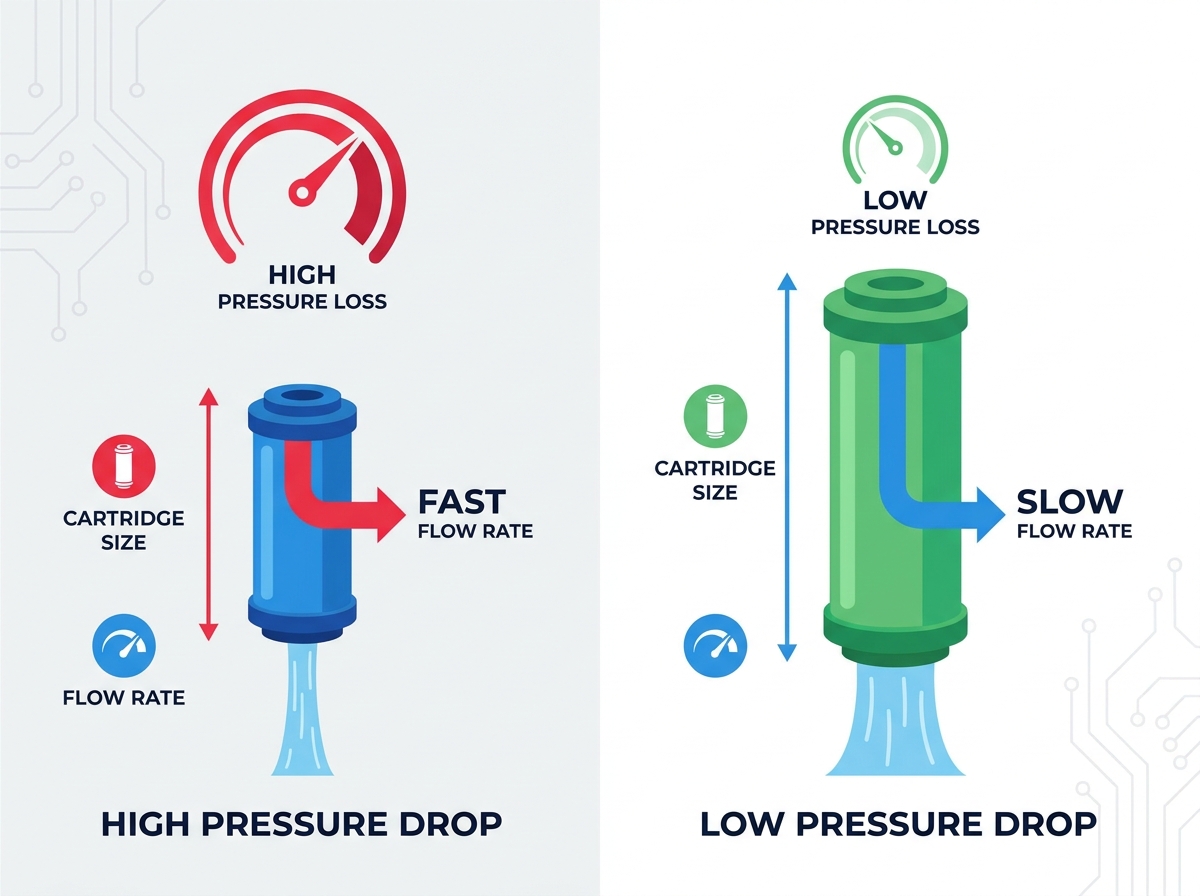
The CTO filter micron rating dictates the physical size of the internal flow channels. Nominal ratings capture most particles of a specific size, offering a balance of flow and filtration. Absolute ratings guarantee a strict cutoff, capturing virtually all targeted particles. A 1-micron block offers significantly tighter filtration than a 5-micron or 10-micron block. However, tighter porosity drastically reduces available flow channels. This directly increases baseline hydraulic resistance from day one. You must balance particulate removal needs against acceptable pressure losses. Specifying a 1-micron block for a system that only requires 5-micron filtration wastes pump energy. It also guarantees premature fouling and unnecessary maintenance interventions. Operators often make the mistake of choosing the tightest micron rating available, assuming it provides better water quality, without accounting for the severe hydraulic penalty.
Assess the incoming water quality and identify the target particulate size.
Determine if the carbon block is acting solely as a chemical adsorber or if it must also perform fine sediment filtration.
Select a 5-micron or 10-micron rating for standard municipal water to minimize pressure drop.
Reserve 1-micron or sub-micron carbon blocks strictly for applications requiring cyst reduction or ultra-fine polishing.
Empty Bed Contact Time (EBCT) measures how long water interacts with the activated carbon. It is the most important metric for adsorption efficiency. Chemical reduction requires sufficient dwell time for the carbon pores to capture chlorine molecules. Without adequate time, chemicals pass through untreated. The required chlorine removal contact time dictates the physical volume of media required. You calculate required cartridge volume based on target flow rates. This ensures necessary contact time to prevent chlorine breakthrough. If your flow rate doubles, your carbon volume must also double to maintain the same EBCT. Ignoring this rule guarantees chemical breakthrough, regardless of the carbon block's initial quality. For standard free chlorine removal, an EBCT of 1 to 2 minutes is standard. Chloramine removal often requires 3 to 5 minutes of EBCT, demanding significantly larger housings.
Cartridge geometry heavily influences hydraulic performance and longevity. Standard 2.5-inch diameter cartridges suit point-of-use or low-flow applications. Upgrading to 4.5-inch Big Blue or high-flow formats drastically changes radial flow dynamics. Increased surface area in larger diameters reduces flux. Flux is the measurement of flow per unit area. Lower flux lowers initial pressure drop and significantly extends service life. Spreading the same volume of water over a larger surface area reduces the velocity through the pores. This slower velocity improves adsorption and delays particulate blinding. When designing a skid, moving from multiple 2.5-inch filters to a single 4.5-inch filter often yields better hydraulic stability.
Cartridge Format | Typical Diameter | Relative Surface Area | Best Application Use Case |
|---|---|---|---|
Standard Slim | 2.5 inches | Low | Point-of-use, low flow residential |
Big Blue (BB) | 4.5 inches | Medium | Whole-house, light commercial |
High-Flow Series | 6.0+ inches | High | Industrial, municipal pre-treatment |
Proper carbon block cartridge sizing also involves selecting the right physical seals. Double Open End (DOE) cartridges rely on flat gaskets and knife-edge seals inside the housing. Single Open End (SOE) cartridges use dual 222 or 226 O-rings for a positive mechanical seal. SOE configurations offer superior system integrity. Proper seal selection prevents fluid bypass. This is especially critical when the system approaches terminal pressure drop. As differential pressure rises, water seeks the path of least resistance. A weak DOE seal will compress or shift, allowing untreated water to bypass the carbon entirely. SOE O-rings maintain their seal regardless of pressure fluctuations. Industrial facilities should mandate SOE configurations for any process where chemical breakthrough causes downstream equipment failure.
Reverse Osmosis membranes are highly sensitive to oxidative damage. Even trace amounts of free chlorine degrade thin-film composite membranes rapidly. A reliable RO prefilter carbon block is mandatory for municipal water sources. You must meet strict pressure requirements for RO feed pumps. Sizing the CTO prefilter correctly prevents pump cavitation. It also avoids low-pressure faults that shut down the entire system. If the prefilter restricts flow too much, the booster pump starves for water. This causes severe mechanical wear and shortens pump life. You must size the carbon block to provide adequate EBCT for chlorine removal while maintaining sufficient feed pressure for the RO pump. We recommend sizing the prefilter to maintain less than a 3 PSI drop at the RO system's maximum recovery rate.
Ultrapure water systems demand exceptional pre-treatment precision. You must optimize adsorption performance while minimizing pressure drop. Sensitive downstream polishing stages rely on this delicate balance. Any pressure fluctuation can disrupt ion exchange resin beds or final membrane stages. UPW systems often utilize high-purity, acid-washed carbon blocks to prevent adding trace minerals back into the water. Sizing these filters requires strict adherence to low-flux principles. You must oversize the housings to ensure the pressure drop remains nearly imperceptible during normal operation. This protects the integrity of the highly sensitive, expensive polishing components downstream. Engineers typically design UPW carbon stages with 100% redundancy to allow for maintenance without interrupting the process flow.
Flow rates exceeding 50 GPM require scalable, robust solutions. Transitioning from multiple parallel standard cartridges to single high-flow cartridge housings simplifies maintenance. It also reduces the footprint of the filtration skid. You should target a mid-life operating pressure drop of 0.4 to 0.6 bar. This equates to roughly 5.8 to 8.7 PSI. This range ensures steady flow without overworking industrial centrifugal pumps. High-flow systems utilize pleated carbon technology or massive extruded blocks. These geometries maximize surface area while maintaining structural integrity under high differential pressures. Proper sizing here prevents costly production downtime during filter changeouts. A single high-flow housing can replace up to ten standard 2.5-inch housings, drastically reducing the labor required for media replacement.
Filtration design is always a conceptual trade-off. You want to maximize flow rate to meet production demands. You also need complete chemical reduction to ensure product quality. Pushing water too fast compromises adsorption kinetics. Slowing water down requires massive multi-round housings. You must find the middle ground for your specific application. This involves calculating the exact EBCT required for your specific contaminant load. Once you establish the minimum contact time, you build the hydraulic profile around that requirement. You cannot sacrifice contact time for higher flow rates without compromising water quality. If a facility needs to double its flow rate, it must install parallel filter housings rather than simply pushing more water through the existing setup.
Industrial and commercial systems rarely operate at a constant average flow. Demand fluctuates based on production cycles or peak usage hours. You must calculate maximum expected flow, known as peak flux. Managing CTO filter pressure loss during these spikes is vital. Ensure the pressure drop remains within the operational tolerance of downstream equipment. If a sudden spike in demand causes a massive pressure drop across the carbon block, downstream equipment may trip on low-pressure alarms. Variable Frequency Drive (VFD) pumps will ramp up aggressively to compensate for this loss, wasting energy and potentially over-pressurizing the housing. Always size your housings and cartridges based on the peak demand flow rate, never the daily average.
Undersizing your carbon filtration leads to frequent, disruptive changeouts. It also causes high energy costs from continuous pump strain. Oversizing requires a higher initial capital expenditure for larger stainless steel housings. However, larger housings accommodate higher dirt loading and extend maintenance intervals. You must analyze the operational implications of both approaches over the system's lifespan. Investing in larger housings upfront usually pays dividends in reduced labor and lower pump maintenance costs. A larger cartridge geometry distributes the particulate load over a wider area, keeping the differential pressure lower for a longer duration. Carbon blocks are designed for adsorption, not dirt holding. Relying on them to capture heavy sediment is an engineering failure.
Using a carbon block as a primary sediment filter is a common but risky mistake. High dirt loading applications will blind the microscopic carbon pores rapidly. This destroys the filter's adsorption capacity long before the carbon is exhausted chemically. We strongly recommend implementing multi-stage filtration. Installing melt-blown depth prefiltration protects the carbon block's porosity. A dedicated 5-micron or 1-micron sediment filter upstream captures suspended solids. This stabilizes pressure drop over time and allows the carbon block to focus entirely on chemical adsorption. This two-stage approach significantly lowers overall maintenance costs and ensures predictable hydraulic performance.
You must install upstream and downstream pressure gauges on every filter housing. This is the only reliable way to monitor CTO filter pressure drop accurately in the field. A standard clean pressure drop target for new installations should remain below 2.0 to 3.0 PSI. The terminal pressure drop threshold is typically 15-20 PSI. Reaching this threshold signals mandatory cartridge replacement. Ignoring this metric leads to severe channeling or catastrophic structural failure of the carbon block. Operating beyond 20 PSI differential forces the pump to consume excessive energy and risks collapsing the filter core. Operators should log these gauge readings daily to track the fouling curve and schedule maintenance proactively.
Excessive differential pressure forces water to find the path of least resistance. It can bypass the cartridge seals entirely if they are not seated correctly. This is a prevalent issue in DOE configurations where gaskets compress over time. High pressure can also create micro-channels within the carbon block itself. Water carves tiny rivers through the media, bypassing the adsorption sites. Both bypass and channeling compromise water quality and allow raw contaminants downstream. Utilizing SOE O-ring seals and strictly adhering to terminal pressure drop limits mitigates these severe operational risks. Once channeling occurs, the pressure drop will falsely appear to improve, misleading operators into thinking the filter is clean while it is actually passing untreated water.
Audit your current flow rates against the manufacturer's pressure drop curves to identify undersized housings.
Install liquid-filled differential pressure gauges across all carbon filter housings to monitor real-time hydraulic performance.
Calculate your exact Empty Bed Contact Time (EBCT) to ensure your carbon volume matches your chemical reduction requirements.
Upgrade to Single Open End (SOE) O-ring configurations for critical applications to eliminate bypass risks at high pressures.
Implement dedicated melt-blown sediment pre-filtration to protect the carbon block from premature particulate blinding.
A: For new installations in low dirt loading applications, the standard clean pressure drop should remain between 2.0 and 3.0 PSI (0.14 to 0.20 bar). Values higher than this at startup indicate the filter is undersized for the current flow rate.
A: There is an inverse relationship between micron rating and flow rate. Tighter micron ratings restrict flow channels, significantly increasing hydraulic resistance and lowering the maximum allowable flow rate compared to a wider micron filter.
A: Chemical adsorption requires a specific dwell time, known as Empty Bed Contact Time (EBCT). This dwell time dictates the physical volume of the carbon block needed. If water flows too fast, chlorine will pass through untreated.
A: You must determine your peak flow rate and the required EBCT for your contaminant. Use these figures alongside manufacturer pressure drop charts to select a cartridge volume and surface area that keeps initial pressure drop below 3.0 PSI.
A: A sudden spike is usually caused by severe particulate fouling or exceeding the filter's dirt holding capacity. This highlights the necessity of installing proper upstream sediment prefiltration to protect the carbon block.
A: Yes, CTO filters are excellent RO prefilters for chlorine removal. However, you must monitor the differential pressure closely to ensure the RO booster pump does not cavitate from restricted feed water flow.